


CNC machining accuracy depends on more than the cutting tool and machine settings. The connection between the machine spindle and the toolholder also plays a critical role in dimensional accuracy, surface finish, vibration control, and overall machining performance. Even a high-quality cutting tool can produce inconsistent results if the toolholder interface does not seat correctly or maintain sufficient rigidity.
Understanding how CNC toolholder interfaces affect spindle performance helps manufacturers reduce runout, prevent premature tool wear, and maintain consistent production quality. Khokhawala Trading LLC, an Industrial Tools Supplier in Dubai, supports industrial businesses seeking suitable tooling solutions for precision machining and manufacturing applications.
In this guide, we explain how toolholder interfaces work, their effect on spindle accuracy, common problems, and practical ways to improve machining performance.
Table of Contents
- What Is a CNC Toolholder Interface?
- How Does the Interface Affect Spindle Accuracy?
- The Relationship Between Toolholder Interfaces and Runout
- Common CNC Toolholder Interface Types
- Signs of Interface Problems
- Factors That Affect Interface Performance
- How to Maintain Spindle and Toolholder Accuracy
- Common Mistakes to Avoid
- Frequently Asked Questions
- Conclusion and CTA
1. What Is a CNC Toolholder Interface?
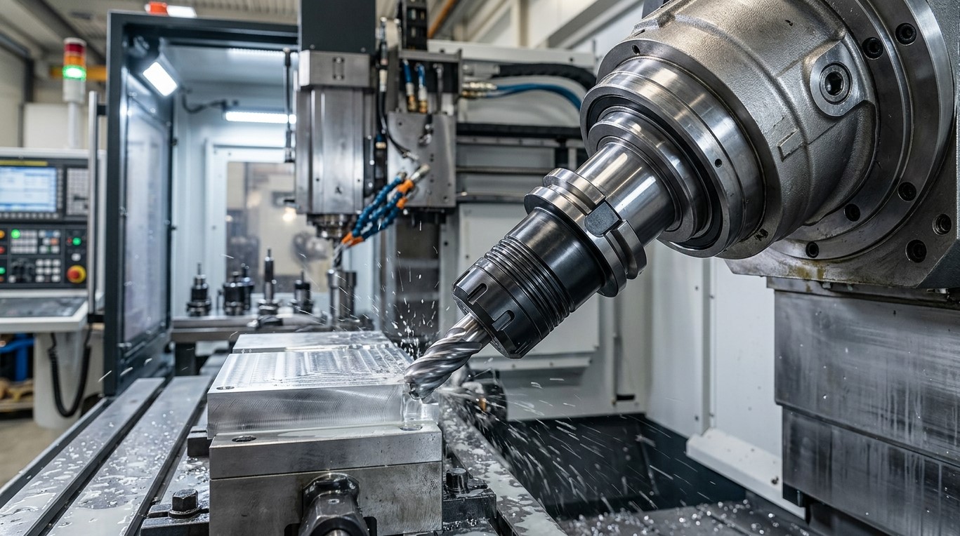
A CNC toolholder interface is the connection between the machine spindle and the toolholder. It positions the holder, transfers rotational force, and helps maintain stability while the cutting tool removes material.
The interface typically includes a precision-machined taper, contact surfaces, and a clamping or retention mechanism. Some systems also use face contact between the holder flange and spindle nose.
Common spindle interface standards include BT, CAT, and HSK. Each has specific dimensions and clamping requirements, so the holder must match the machine spindle.
The toolholder also has a second interface where it grips the cutting tool. Both connections influence the accuracy of the complete spindle-to-tool assembly.
2. How Does the Interface Affect Spindle Accuracy?
The spindle interface affects how accurately the cutting tool rotates around the intended centerline. Proper contact and clamping help the toolholder seat consistently and resist movement during machining.
Accurate Tool Positioning
A correctly manufactured and properly seated interface helps position the toolholder concentrically with the spindle. This supports repeatable tool positioning after tool changes.
Improved Rigidity
A stable interface resists bending and movement under cutting forces. Greater rigidity can reduce vibration and help maintain dimensional accuracy.
Consistent Surface Finish
When the toolholder remains stable, the cutting edges engage the workpiece more consistently. This can reduce unwanted surface marks caused by vibration or uneven cutting.
Better Tool Life
Poor seating or excessive runout can cause some cutting edges to carry more load than others. This uneven loading can accelerate wear and lead to premature tool failure.
Reduced Spindle Wear
Contamination, damaged contact surfaces, and poor retention can affect how forces transfer between the holder and spindle. Regular inspection helps prevent avoidable wear and damage.
3. The Relationship Between Toolholder Interfaces and Runout
Runout is the amount by which a rotating tool or component deviates from its intended rotational axis. It is commonly measured using a dial indicator, with total indicator reading representing the difference between the maximum and minimum readings.
The spindle-to-toolholder interface is one potential source of runout.
What Causes Interface-Related Runout?
- Chips or dirt trapped between mating surfaces
- Scratches, dents, or burrs on the taper
- Worn or damaged spindle contact surfaces
- Incorrect or incompatible toolholders
- Problems with the retention mechanism
- Poor manufacturing accuracy
- Improper seating or clamping
Even small amounts of contamination can prevent full contact and shift the holder from its intended position.
Runout can also originate from the toolholder’s internal clamping system, collet, cutting tool shank, or spindle bearings. Therefore, it is important to inspect the entire assembly rather than assume the interface is always the cause.
4. Common CNC Toolholder Interface Types
Different interfaces are designed for specific machine platforms and machining requirements.
BT Toolholder Interface
BT toolholders commonly use a 7:24 steep taper and an external retention knob. They are widely used in CNC machining centers, particularly in Asian manufacturing markets.
Their performance depends on correct spindle compatibility, taper condition, clamping force, and the quality of the complete tool assembly.
CAT Toolholder Interface
CAT toolholders also use a 7:24 steep taper but have different flange and retention details from BT systems. They are widely used in North American machining environments.
BT and CAT holders should not be treated as interchangeable simply because they have the same nominal size.
HSK Toolholder Interface
HSK holders use a hollow 1:10 taper and an internal clamping mechanism. Many HSK designs provide contact at both the taper and spindle face.
This dual-contact arrangement can offer advantages in rigidity and repeatability when the holder is matched with a compatible spindle.
Dual-Contact Systems
Some toolholder systems are designed to make contact at both the taper and the spindle face. When properly matched, these systems can improve support and rigidity.
However, actual performance depends on the specific interface standard, spindle design, and operating conditions.
5. Signs of Interface Problems
Interface issues may appear as machining defects, unusual vibration, or inconsistent results between tool changes.
Excessive Vibration or Chatter
Unstable contact or insufficient rigidity can contribute to chatter during cutting.
Poor Surface Finish
Repeated surface marks, waviness, or inconsistent finishes may indicate runout, vibration, or poor tool seating.
Dimensional Inconsistency
If a part’s dimensions change unexpectedly between operations or tool changes, the interface and complete tool assembly should be inspected.
Unusual Taper Wear
Fretting marks, corrosion, scratches, or dents may indicate contamination, movement, or poor contact.
Premature Tool Wear
Uneven cutting-edge wear may result from excessive runout or instability in the spindle-to-tool connection.
These symptoms do not automatically prove that the interface is defective. Tool condition, spindle bearings, workholding, cutting parameters, and machine geometry should also be considered.
6. Factors That Affect Interface Performance
Several factors determine how well the spindle and toolholder work together.
Cleanliness
Both the spindle taper and the holder’s mating surfaces must be clean. Chips, dried coolant, oil residue, and dirt can interfere with seating.
Surface Condition
Nicks, dents, corrosion, and fretting can reduce contact quality. Damaged precision surfaces should be evaluated before the holder is returned to service.
Clamping Force
The retention mechanism must provide the clamping force specified by the machine manufacturer. Insufficient or inconsistent clamping can compromise stability.
Manufacturing Tolerances
The spindle and toolholder must meet their relevant dimensional and geometric specifications. Poor concentricity or incorrect dimensions can increase runout.
Spindle Speed and Thermal Effects
At higher rotational speeds, centrifugal forces and temperature changes can influence how some interfaces behave. The holder and spindle must be suitable for the intended operating speed.
Tool Length and Cutting Forces
Long tool assemblies can increase deflection and vibration. Even a precise interface cannot fully compensate for excessive tool projection or unsuitable cutting conditions.
7. How to Maintain Spindle and Toolholder Accuracy
Regular maintenance helps preserve interface performance and reduce machining problems.
Clean Contact Surfaces Before Installation
Use an appropriate lint-free cloth and manufacturer-approved cleaning procedure. Avoid methods that scratch or damage precision surfaces.
Inspect the Spindle Taper and Holder
Look for wear, dents, burrs, corrosion, and unusual contact marks. If damage is suspected, arrange an appropriate inspection.
Measure Runout
Use suitable measuring equipment to check runout at consistent locations. Comparing readings near the holder and closer to the cutting tool can help identify where the error is introduced.
Check the Retention Mechanism
Inspect pull studs, retention knobs, and drawbar-related components according to the machine manufacturer’s maintenance instructions.
Use Compatible Toolholders
Confirm the interface standard, size, retention components, and any required coolant arrangements before installing a holder.
Minimize Tool Projection
Use the shortest practical tool assembly that provides adequate access to the workpiece. This helps reduce deflection and improve stability.
Follow Maintenance Schedules
Routine spindle inspections and maintenance can identify wear before it leads to major accuracy or production problems.
8. Common Mistakes to Avoid
Avoid these mistakes when working with CNC toolholder interfaces:
- Installing a holder with the wrong spindle interface
- Ignoring chips or coolant residue on contact surfaces
- Continuing to use a holder with visible taper damage
- Assuming every vibration problem originates from the spindle
- Ignoring runout measurements
- Using incorrect retention components
- Operating a holder beyond its rated speed
- Overlooking spindle maintenance
- Using unnecessarily long tool assemblies
A systematic inspection process can help identify the actual cause of poor machining performance before components are replaced unnecessarily.
9. Frequently Asked Questions
How does a CNC toolholder interface affect machining accuracy?
It determines how accurately the holder seats in the spindle and how effectively the assembly resists movement. Poor contact or contamination can increase runout, vibration, and dimensional variation.
Can a dirty spindle taper cause runout?
Yes. Chips, oil residue, dried coolant, and other contaminants can prevent proper seating and shift the holder away from its intended position.
What is the difference between BT, CAT, and HSK interfaces?
BT and CAT generally use 7:24 steep tapers with external retention systems, while HSK uses a hollow 1:10 taper and internal clamping. Their dimensions and retention arrangements differ, so compatibility must be verified.
Does low runout guarantee accurate machining?
No. Low runout is important, but accuracy also depends on spindle condition, machine geometry, cutting tool quality, workholding, thermal effects, and machining parameters.
How often should toolholder interfaces be inspected?
Cleanliness and visible condition should be checked before use. More detailed measurements and maintenance should follow the machine manufacturer’s recommendations and the accuracy requirements of the application.
Can a damaged toolholder affect spindle life?
Yes. A damaged or poorly seated holder can contribute to abnormal contact, vibration, and wear. Inspect questionable components before continuing production.
How can I determine whether runout comes from the spindle or toolholder?
Clean and inspect the contact surfaces, then measure the system methodically using suitable equipment and a test arbor where appropriate. A qualified technician can help isolate spindle, holder, and cutting-tool errors.
10. Conclusion and CTA
CNC toolholder interfaces play an essential role in spindle accuracy, rigidity, vibration control, and machining consistency. A properly matched, clean, and well-maintained interface helps the cutting tool rotate accurately and supports reliable production.
To maintain performance, inspect taper surfaces, verify compatibility, check runout, maintain the retention mechanism, and follow recommended spindle maintenance procedures. Remember that the complete spindle-to-tool assembly contributes to accuracy, so investigate all relevant components when problems occur.
For practical industrial tooling solutions, Khokhawala Trading LLC supports businesses seeking suitable tools and accessories for their machining requirements. As an Industrial Tools Supplier in Dubai, Khokhawala Trading LLC aims to help workshops and manufacturers make informed tooling choices for their operations.
Looking to improve CNC machining accuracy and performance? Choose compatible toolholding solutions, maintain clean spindle interfaces, and inspect your tooling regularly to support consistent, dependable results.
About The Author